Blog 01 - CA18DET rear sump oil pan
I had some time this past summer to completely re-do the oil pan and pickup design on my engine swap. For those that don't know, CA18's originally came as a front sump engine, which is not compatible with the FC chassis... This is probably the most annoying part of putting a CA into an FC in my opinion.
I've had the CA18 engine in the car with a pretty hacked up oil pan and pickup for the last 7 years or so. It's been modified several times over the years, with the last addition being a trap door sump added a few years back.

When I first built the pan (above, circa 2017), my skills and access to tools were not at the level they are now, so it had quite a few issues; leaking from the flange from welding warpage, pickup tube hanging too low and hitting the steering rack (cracked 2 steering rack hard lines because of this), leaky welds, leaky oil drain port, the list goes on...
The engine was already out for a forged rebuild and head drains, so it was time to get to work fabricating a new pan.
First step was to cut my old work off from the factory flange, then stick it on the the milling machine to surface it:

I had just enough travel on the Y axis to machine the length of it. The X axis didn't quite have enough travel so I had to reposition my plywood jig to machine each side separately.

Now that I had a decently flat surface to work from, it was time to begin fabrication.
I decided to try and make the pan from only 3 pieces of 18g sheet metal. This way, I thought it would minimize the chance of leaks and warpage due to less welding involved.
I drew up the sides a little oversize in CAD, then cut them out on the plasma table. I carefully bent the sides around, following the contours of the CA18 pan.


It was now time to make the 3rd piece, the bottom.
I started off with a cardboard template for this one:

From this I created a CAD drawing:

Then cut it out on the plasma table:

And after bending it to fit the sides, it looked like this:

I tacked this bottom panel onto the oil pan, assembled it on my forged block, then dropped it in one last time to check the fitment and clearances:
![]()
Perfect! I felt now like I had the hard parts taken care of. It was looking something like this before welding:


I double checked that the flange had stayed straight and flat - it was OK, but there were a couple areas that needed a bit of flattening out with a mallet and block of wood.
The alignment of all the bolt holes looked good, so I bolted it down to my spare block and proceeded to slowly TIG weld it all up:

To avoid warpage:
I welded it up in 1" passes, blasting each pass for around 5-10 seconds with compressed air immediately after welding. I had around 6-8 different weld start areas around the pan - this was to try and keep the heat evenly dispersed, as I moved to a different area for each weld.
Although time consuming, this worked very well... the final result after a couple hours under the hood:


It was now time to work on the pan's extra features. I started with adding an M12 oil drain port, with a bung I turned on the lathe:

Drilled a hole at the back of the pan, then welded the bung in place:

Next up was to add the -8 AN drain ports for the head drains. I opted to route them to the intake side of the engine - this keeps the drain lines away from all the heat created on the turbo's side.

Huge thanks to Nick Murray in Australia for sending me one of his last low-profile head drain kits for the CA18DET.

As you can see - it's a tight fit but it works.
I am keeping the OEM oil pan's 5/8" port for the turbo oil drain, so that's it in terms of ports and fittings.
Next up was the oil pan's insides. I started from the bottom up, and made a new adaptor plate to mount my previously made trap door baffle setup:

Here's the trap door enclosure tacked onto the new adapter plate:

And it all installed in the new oil pan:

After this was done, it was time to finish the oil pickup tube before proceeding. After some tricky measurement, I got another elbow tacked onto the main length of the tube at the correct angle and depth:

Then I tacked on the OEM pickup filter, and test fitted the pan:


Everything looked pretty good, soooo...


The material was 304 stainless so I needed to back-purge it. Got it all welded up!
Unfortunately, I was rushing and welded the flange up too fast...
It warped really bad, so I needed to use my belt sander to flatten it out - this removed most of the groove for the sealing o-ring, so it needed to be put in the mill and a new o-ring groove bored out:


With that fixed, I went on to build a windage tray... which is basically a screen that sits below the the crankshaft to help catch oil that is flung off of the crankshaft, and break it up so it drizzles down to the sump.
This first one didn't end up fitting well, but gives you the idea:

After modifying the drawing a bit, I cut out the winner:

Tabs were placed in strategic positions to secure the windage tray to the oil pan sides with tack welds, as was done for the trap door baffle.
The slots were bent using a flathead screwdriver and a pair of pliers. They are bent in a direction that catches the oil flung off the crankshaft rotation. I used similar slot dimensions as the OEM pan, and spaced them out where they would fit.

Since the crank will be flinging oil directly towards my head drain ports, I made a small baffle cover for these (pictured above).
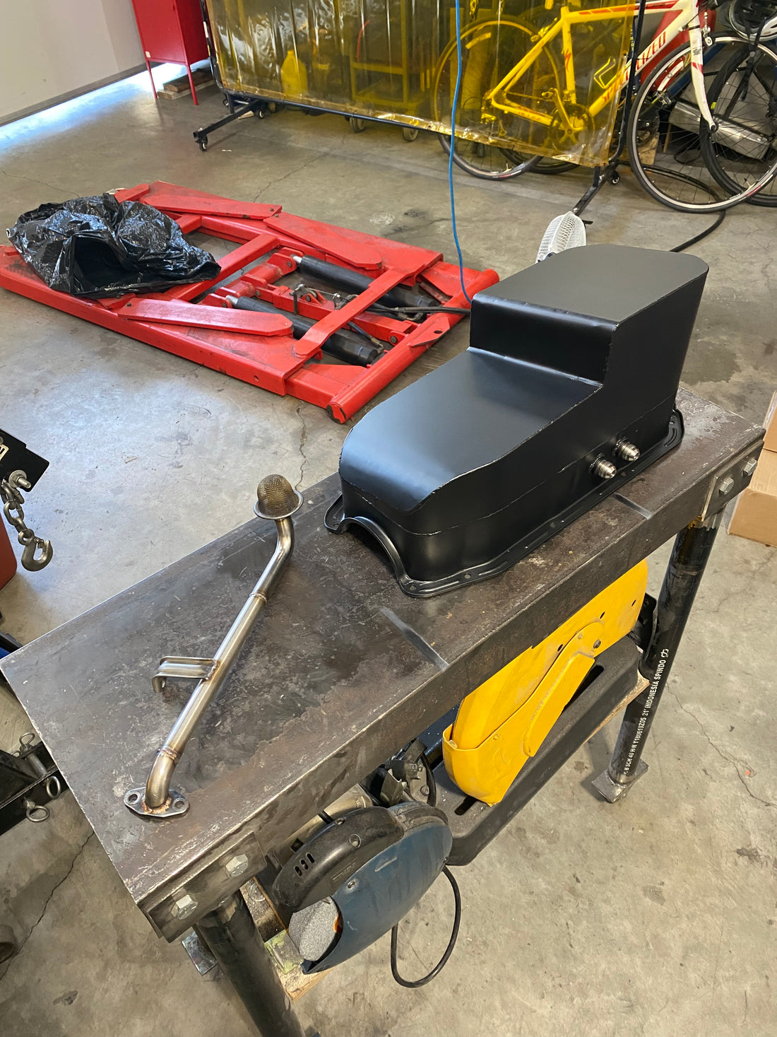
Below is a picture of the finished fab-work for the oil pan and pickup tube. It's a tight fit, but the oil pan just slides over the pickup tube and all holes line up to the engine block. The oil dipstick also functions like OEM still.

It was now time to do a leak test. I did not want this new engine to have any leaks what-so-ever... I had some diesel laying around, so I filled the pan up as full as I could and left it for a few days on my work bench:

Luckily, there were no leaks!

Being able to focus the tight TIG arc directly on the seam of the 2 metals and see what is going on through a nice helmet was the key to my welding success. I gave a bit of extra time on my stop/starts just to make sure I was burned into the connecting weld.
All that was left to do is scuff the pan up with a maroon scuff pad (400 grit), clean it, and give it a few coats of engine enamel:


Left it to cure for a few days, then assembled it to the new engine using OEM Nissan sealant:

And got it bolted and torqued down to the block with new rubber seals:

Lastly, I made some lines up for the head drains:


And that's a wrap. Thanks for reading!

1 comment
Hi. I have a high power Ca18 and I would like to know if you still makes the oil pan for then?